

- Product description
-
The concept of bowl-lock scaffolding
• The cup-lock system consists of components such as steel pipe uprights, crossbars, and cup-lock joints. Its basic structure and installation requirements are similar to those of hook-type steel tube scaffolding, with the main difference lying in the cup-lock joint itself.
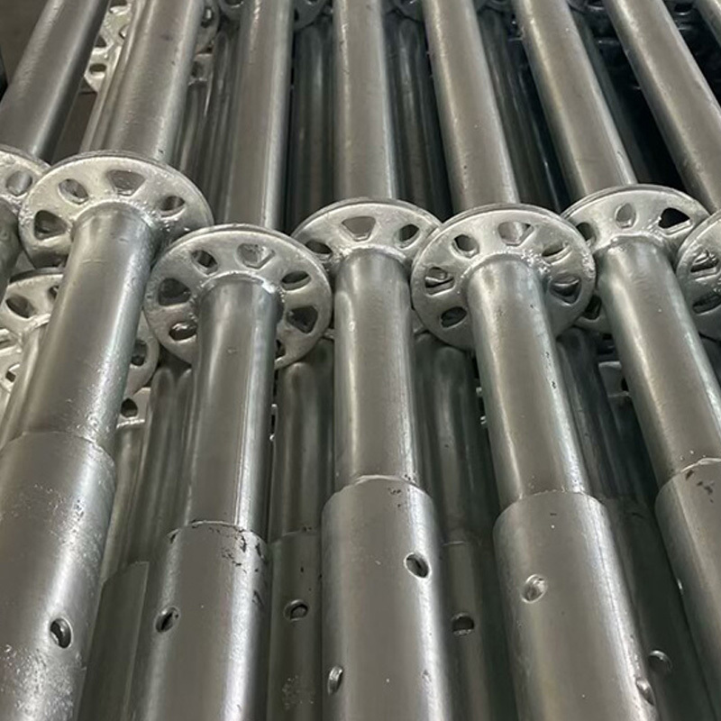
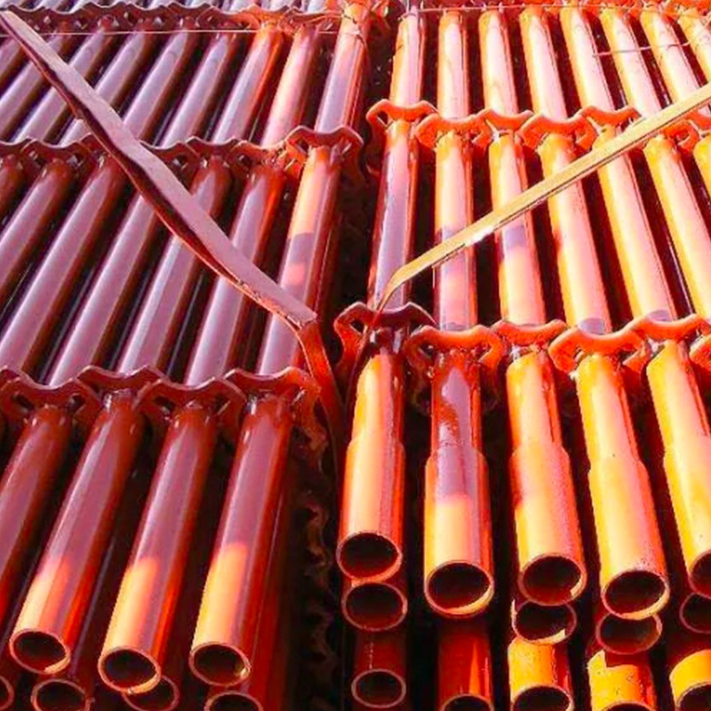
• The bowl-type connector consists of components such as the upper bowl buckle, lower bowl buckle, crossbar joint, and upper bowl buckle positioning pin. The positioning pins of the lower and upper bowl buckles are welded onto the upright post, with the upper bowl buckle fitted over the post. The plugs are welded onto the crossbars and diagonal braces. During assembly, insert the crossbars and diagonal braces into the lower bowl buckle, press down and rotate the upper bowl buckle, then secure it in place using the positioning pin.
• Cup-lock steel tube scaffolding features a horizontal distance of 1.2m between uprights, while the longitudinal spacing can be adjusted based on the scaffold’s load capacity to 1.2m, 1.5m, 1.8m, or 2.4m. The step distance is either 1.8m or 2.4m. When erecting the uprights, their joints should be staggered. For the first layer of uprights, rods measuring 1.8m and 3.0m in length should be arranged alternately; for upper layers, uniformly use 3.0m-long rods. Once reaching the top level, recombine two shorter rods—1.8m and 3.0m—to achieve proper leveling.
• The verticality deviation of scaffolds with a height less than 30m should be controlled within 1/200, while for supports taller than 30m, the verticality deviation should be maintained between 1/400 and 1/600. The overall verticality deviation of the entire scaffold should not exceed 100mm.
Characteristics of bowl-lock scaffolding
Key features:
• The joint structure of the bowl-type multifunctional scaffolding is reasonably designed, features a simple manufacturing process, offers convenient operation, and boasts a wide range of applications. Compared to traditional folding systems, the bow-type multifunctional fold boasts the following outstanding features:
• The bowl-lock joint features a rational structure: the load-transmitting rods transfer forces axially, giving the scaffolding an overall high structural strength and excellent three-dimensional spatial stability, thereby meeting construction safety requirements.
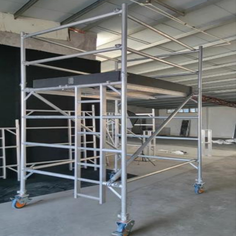
• Flexible scaffolding assembly templates. This includes 0.6m single-row scaffolds, double-row scaffolds, support frames, and various assembled materials designed for lifting and load-bearing applications—combining to form versatile construction equipment. These systems can also be arranged in curved shapes and used on surfaces with differing heights. Additionally, the spacing of the scaffolding can be adjusted according to
• Different load requirements call for flexible adjustments. All components of the cup-lock scaffolding system share uniform dimensions, ensuring that the erected scaffolds are standardized and highly organized.
• It boasts high assembly and disassembly efficiency, reducing labor intensity. Assembly and disassembly speeds are 3 to 5 times faster than those of hook-type scaffolding.
• It eliminates bolt operations, making it less likely for scattered parts to get lost. The components are lightweight yet robust, ensuring safe and reliable use. Generally speaking, rust does not affect assembly and disassembly processes; moreover, they are easy to maintain and convenient for transportation.
• It can be retrofitted using existing coupler-type steel pipe scaffolding, significantly reducing the costs of upgrading and replacement.
Bowl-type scaffolding pole accessories and their applications
(a) Solid rods: These are fabricated by attaching a 0.6-meter-long curved rod to a sleeve-shaped piece with a diameter of 48 mm x 3.5 mm, and then welding a vertical connecting tube to the top end. They serve as the vertical load-bearing members of the scaffolding system.
(b) Top rod (vertical top rod): Equipped with a vertical rod connection pipe at the top, these rods are used to support the low insertion of the supporting posts. They serve as vertical load-bearing members at the tops of supporting frames (columns), material-lifting frames, and similar structures.
(c) Crossbar: Made by welding a 48mm x 3.5mm sawn steel bar to both ends of a ceramic-length steel pipe, serving as a horizontal connecting tube between upright posts or functioning as a horizontal load-bearing bar for the frame.
(d) Single horizontal bar: Horizontal bar connection ends equipped with 48mm x 3.5mm steel tubes. These are used as horizontal crossbars for single-row scaffolding.
(e) Diagonal braces: Manufactured by riveting diagonal brace connectors to both ends of a 48mm-diameter x 3.5mm-thick sleeve. These are used to enhance the stability and strength of the scaffolding, thereby improving its load-bearing capacity. Diagonal braces should be positioned as close as possible to the frame nodes.
(f) Base: Manufactured by welding a connecting rod through the center of a 150mm x 150mm x 8mm sleeve plate. These are positioned at the base of the upright post, serving to prevent swaying of the post and to distribute/transfer the upper loads to the foundation.Key Points for Construction Control of Cuplock Scaffolding
Product Name Commonly Used Models Specifications (mm) Theoretical Weight (KG) Erect the pole LG-120 ⌀48 × 1200 7.05 LG-180 ⌀48 × 1800 10.19 LG-240 ⌀48 × 2400 13.34 LG-300 ⌀48 × 3000 16.48 Horizontal bar HG-30 ⌀48 × 300 1.32 HG-60 ⌀48 × 600 2.47 HG-90 ⌀48 × 900 3.63 HG-120 ⌀48 × 1200 4.78 HG-150 ⌀48 × 1500 5.93 HG-180 ⌀48 × 1800 7.08 Crossbar JHG-90 ⌀48 × 900 4.37 JHG-120 ⌀48 × 1200 5.52 JHG-120+30 ⌀48 × (1200 + 300) 6.85 JHG-120+60 ⌀48 × (1200 + 600) 8.16 Diagonal bar XG-0912 ⌀48 × 1500 6.33 XG-1212 ⌀48 × 1700 7.03 XG-1218 ⌀48 × 2160 8.66 XG-1518 ⌀48 × 2340 9.30 XG-1818 ⌀48 × 2550 10.04 Product Name Commonly Used Models Specifications Theoretical Weight (KG) Dedicated diagonal brace ZXG-0912 ⌀48 × 1270 5.89 ZXG-0918 ⌀48 × 1750 7.73 ZXG-1212 ⌀48 × 1500 6.76 ZXG-1218 ⌀48 × 1920 8.37 Narrow Cantilever Beam TL-30 Width: 300mm 1.53 Wide Cantilever Beam TL-60 Width: 600mm 8.60 Pole-Connecting Pin LLX ⌀10 0.18 Adjustable base KTZ-45 T38×6, adjustment range ≤ 300mm 5.82 KTZ-60 T38×6, Adjustment range ≤ 450mm 7.12 KTZ-75 T38×6, adjustment range ≤ 600mm 8.50 Adjustable Support Beam KTC-45 T38×6, adjustment range ≤ 300mm 7.01 KTC-60 T38×6, Adjustment range ≤ 450mm 8.31 KTC-75 T38×6, adjustment range ≤ 600mm 9.69 Scaffolding board JB-120 1200 × 270 12.80 JB-150 1500 × 270 15.00 JB-180 1800 × 270 17.90 Main dimensions and general specifications of cup-lock scaffolding
Serial Number Project Name Regulatory requirements 1 Structural facade Ordinary scaffolding with a height H ≤ 20m should be erected using conventional methods; scaffolding taller than H > 20m must undergo specialized construction design and structural calculations. 2 Load Limit Construction scaffolding must not exceed 2.7 kN/m²; decorative scaffolding should be between 1.2 and 2.0 kN/m², or determined based on actual conditions. 3 Basic Practices The foundation should be leveled, compacted, and equipped with drainage measures. Vertical posts must be fitted with base plates, and 0.05m × 0.2m × 2m wooden scaffold boards should be laid down. For scaffolds taller than 40m, a foundation calculation must be performed, and appropriate laying measures must be determined. 4 Vertical spacing of upright posts Typically between 1.2 and 1.5 meters. If it exceeds this range, a verification calculation is required. 5 Vertical post lateral spacing ≤ 1.2 meters 6 Fastener All high-rise scaffolds with a height H > 30m must have their lower half (H/2) supported by toothed bowl-type connectors. Construction preparations before scaffolding erection:
① Level the site ground. To ensure the scaffolding is safe, stable, and neatly arranged after erection, it is essential to compact and flatten the ground thoroughly. According to the installation requirements, place full-length base plates with a thickness of 50 mm. Make sure the base plates are firmly in contact with the ground. Next, position the upright posts according to the specified spacing guidelines—mark their exact locations clearly with a pen—and carefully set the post bases precisely at these marked spots, ensuring that each base is centered squarely on its corresponding plate.
② Place the sweeping pole and then erect the upright pole. Before starting to raise the upright pole, first prepare the horizontal bar, position it in place, and join multiple sections together to extend its length, before finally standing the upright pole upright.
Product Application
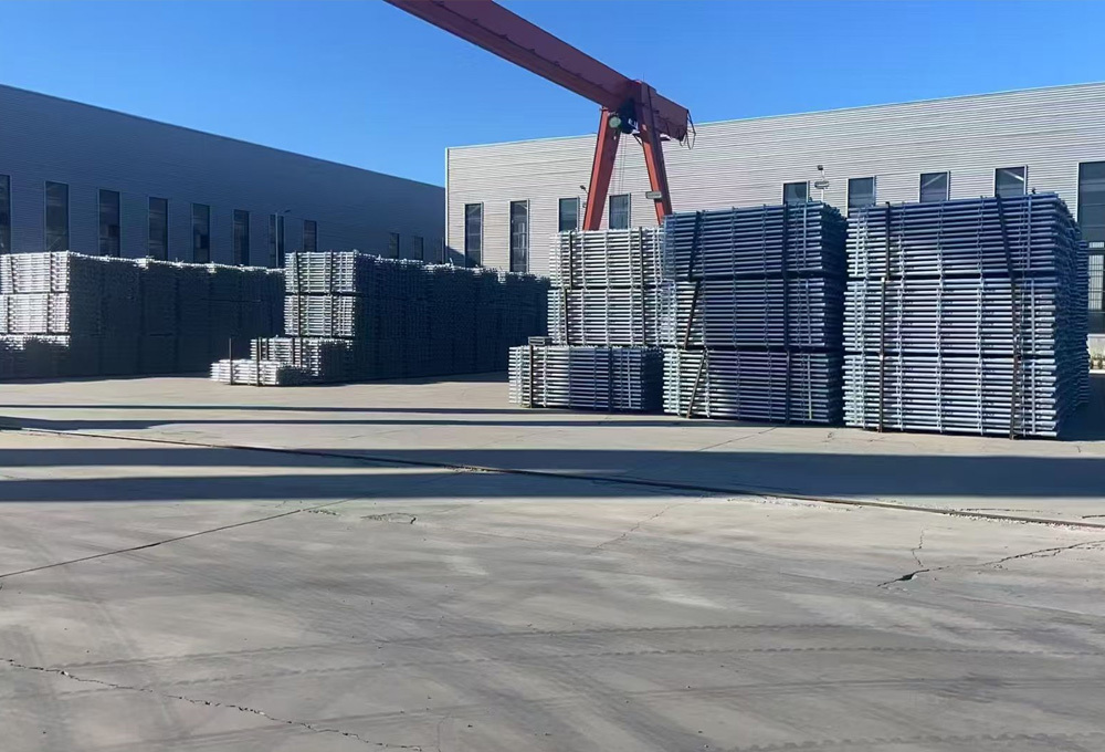
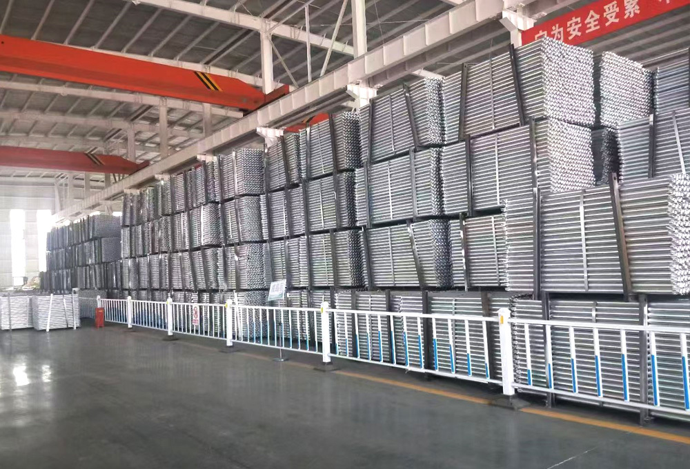
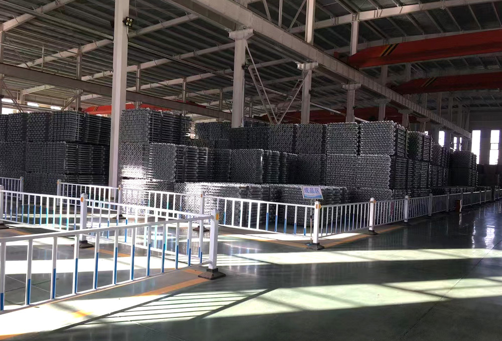
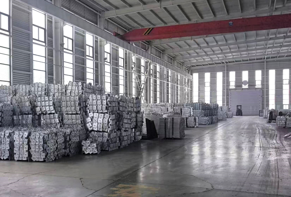
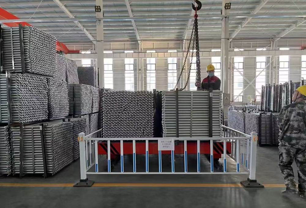
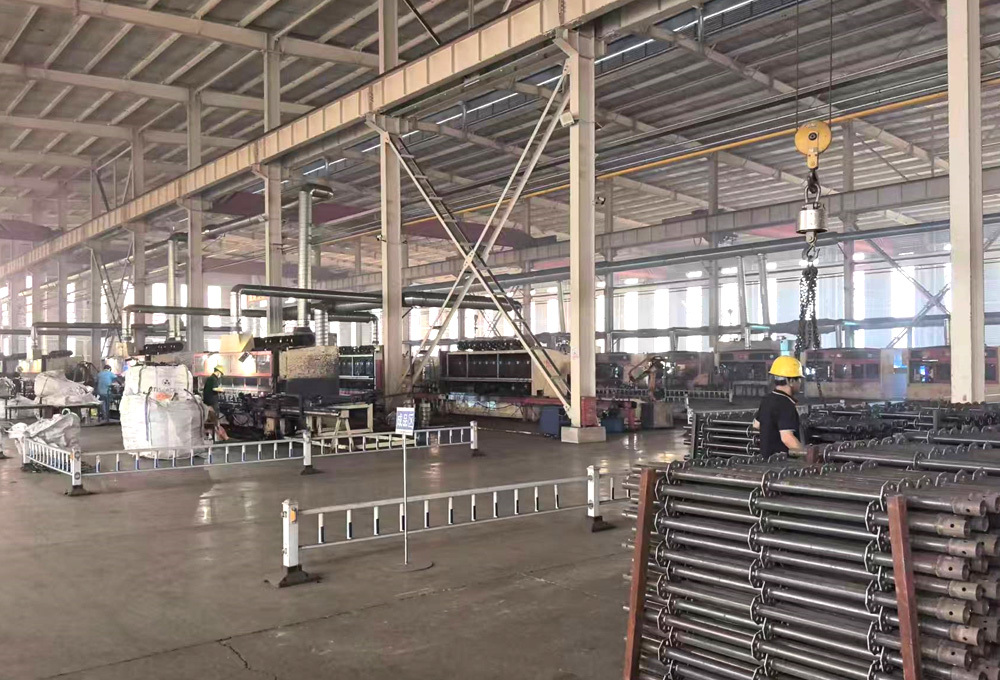
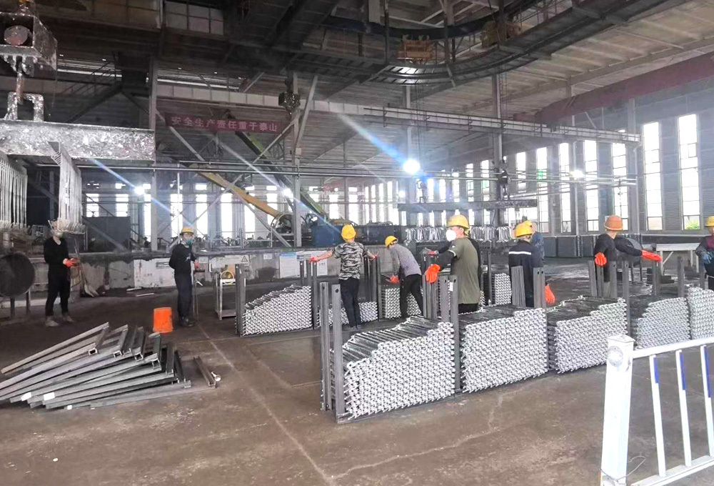
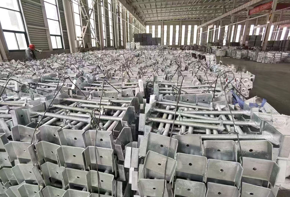
Production
Customization
Customer Inquiry
Factory Quotation
Customer Orders
Factory Production
Quality Testing
Packaging & Shipping
FAQ
Can you accept small quantities?
Yes, accept small quantity, fast delivery
Do you have pre-shipment inspection procedures?
Yes, we always test the products before delivery.
Can I take samples for testing?
Yes, samples can be sent for testing before bulk ordering.
When is the delivery time?
Inventory orders within 7-15 days, for oem and odm orders, the specific time depends on the actual situation.
What are the terms of payment?
Wire transfer or letter of credit, Western Union, Alipay, etc.
What is the minimum order quantity?
It depends on the product.
Packing and shipping


Previous:
Next:


Bowl-lock scaffolding
If you need customized delivery products, Contact US !
Products Category
Tag list
Request a Quote
We will contact you within one working day. Please pay attention to your email.


